E3.1: Making Modern Retro Computer Terminals
The trials and tribulations of prototyping ridiculously cute and complex systems!
Making Modern Retro Computer Terminals
During the 2020 Covid-19 Pandemic, I found myself with plenty of spare time (I am currently willingly unemployed), the inability to go anywhere, and a curiosity about making real physical objects. I had a 3D printer that I previously used to create simple parts and enclosures here and there, but I was keen on moving onto trickier objects, beyond the spectrum of basic blocky parts and random things downloaded from Thingiverse.
I also often fantasized about owning a minimalistic physical terminal, a single appliance-like device you could just turn on, and get a fully working linux shell. I learnt to code C on a dumb terminal back when I was at university, and there’s some nostalgia attached to them for me. I regularly looked on eBay and similar local sites, looking for an old dumb terminal in good visual condition that I could hack into, at a reasonable price, but I never quite found the right one.
At some point, these curiosities and dreams unified into a formal project: Why not make a fully functional terminal myself? And so it began...
Where to Start - Choosing the right tool for the job
A lot of things are needed to create a CAD physical object from scratch; one of the first ones is a CAD tool, and enough knowledge to use it. My process started there, trying to find and choose the right tool for the job. I looked into the available tools (preferably free), curious about how things changed since the last time I got my hands into 3D modeling (I was pretty good at 3D Studio Max 2.5, around 15 years ago). I also heard a lot about parametric and timeline-based modeling, and I quickly saw why. I landed on Autodesk Fusion360, and I started using the tool. As with most CAD tools, there is no immediately obvious way to do a lot of the things you want to achieve. This happened a lot, and it's always a frustrating process. But with enough time and persistence, everything starts to click. Sometimes just browsing the available toolbars and menus is enough for you to find what you are looking for, but sometimes it requires following YouTube tutorials.
In my opinion, the most liberating feature of this new generation of tools is having a non-destructive timeline. On traditional modeling tools, your current actions often "destroy" the work you put on previously, so as you build your model incrementally (which is often the only way to do so), you are also destroying previous steps. This is not so much of a problem if you know exactly what you want to model as you start, because if you know the tool well enough you can plan every step ahead and be fairly confident that your design will require no foundational changes later one... But if you don't quite know what you want to model, and just want to experiment with shapes to see what works and looks best, "rolling back" into earlier steps often means losing hours of tedious work... Which I believe consciously or unconsciously limits the amount of experimentation you are willing to do.
Coming from a strong software background, the parallels are pretty obvious: Modeling with a non-destructive CAD tool is like writing code with a version control system. When programming, if you feel confident in your version control system and your skills using it, you know that no matter how badly you mess up your codebase, you can always reliably roll back into a previous state of your project safely. With this safety in the back of your mind, you immediately become more willing to try new things (that may or may not lead to improvements, but at least you are trying out new things and learning from the outcomes). If you can try different things at the same time with branches, even better, but this is not something I have been able to do in Autodesk Fusion 360.
There are some truly amazing features available in these modern CAD tools, like very simple customizable bezels, painless boolean operations between bodies, projection of 3D objects / parts into 2D slices, etc. All of these took a lot of trial and error to learn (especially because I am fairly stubborn, and I defer looking at manuals as long as I can). As a result, lots of the features of the software were only learnt as they were needed, and this is never a great setup for a project… You often realize there was a better way to do this or that once you go back to older parts of the project.
Some inspiration
It’s always a good idea to have a look at what has been done before, to both see what you like and also what you don’t like. I spent a few days searching for historical computer designs on the internet, keeping screenshots of what I liked. I also bought a couple books I found on the subject. Some of these old machines look absolutely incredible. Some aged better than others, but there’s something to learn from all of them.
What to make and what to source?
A computer terminal consists of a few things, and not all of them can be made "at home". I had to decide what I was willing to create from scratch, and what components I would have to source.
I sourced all electronic components, including the keyboard. I quickly realized the LCD needed to be chosen first, as it is the most structurally constraining element; its dimensions will entirely dictate the design. Choosing an LCD is an adventure of its own. I found two ways of tackling this. The first one consists of picking your desired specs and dimensions, and seeing if such a thing exists (http://panelook.com is a good site for this). If it does, seeing if it can be bought somewhere (and they don’t require you to buy hundreds), and making sure that the price is not astronomical.
As you read this, you probably noticed there’s a lot of “AND” conditionals… If you did, yes, your instincts were right. The stars just never seem to align in the right way... Which led me to the second way of choosing the LCD: Just look at what can be bought, browse LCD listings for hours on Aliexpress, and adapt your designs to what you can find. The chosen LCD for the computer I’m focusing this article on ended up being a 1920x480 8.8-inch IPS LCD (a quite unusual 4:1 aspect ratio), which gives the computer a very unusual look.
I originally fancied the idea of making my own mechanical keyboard, but I wasn't sure the finish with my 3D printer would be good enough for keycaps… And combining purchased keycaps with a 3D printer case would not have looked great. I would have had to split the case in two parts as well (too large for a single print on my 220cm printer bed), which would also have looked awful for a keyboard. After some exhaustive searching, I found good options out there (even with my bizarre ISO Spanish layout requirements), so I stuck to that.
Another key component to pick was the single-board computer, which holds all the software needed to run the experience. A Raspberry Pi seemed like the obvious choice; but I found out that something with a beefier GPU is very welcome to drive higher-resolution LCDs. For the “Ultrawide” computer I’m centering this article around, I chose the 2GB Nvidia Jetson Nano, as it is affordable and it can run full desktop OpenGL (vs. the mobile oriented OpenGL ES on the Raspberry Pi). As a bonus, I can run some graphically heavy desktop Interactive projects on the small computer, often with minimal porting efforts.
Designing the enclosure
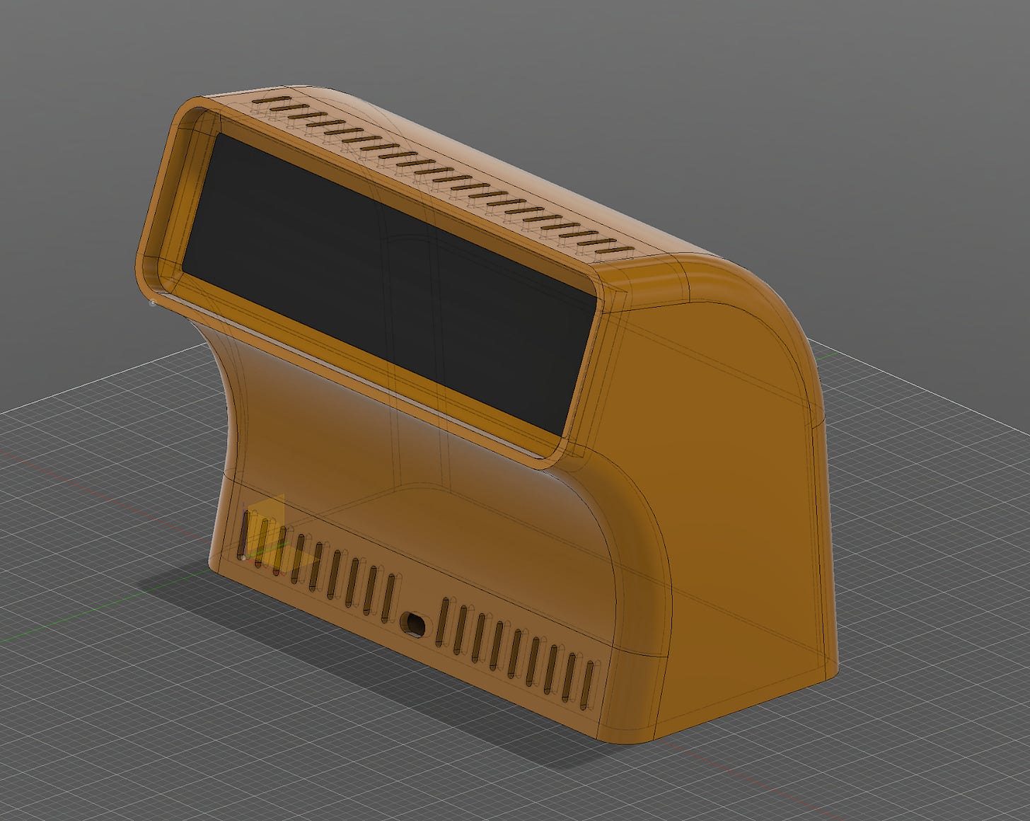
This is where the conflicts begin. I will use the “Ultrawide” computer terminal I created to illustrate this, but obviously every design will require different avenues. I usually start with a lateral extrusion of a rough 2D shape, keeping in mind the LCD dimensions (including the bezels around the panel) as a reference.
Then I choose the thickness of the whole object, to turn the volume into a hollow object (in this case 4 mm). I adjust the shape to make sure the LCD and its frame (which is usually horizontally and vertically asymmetrical) fit in the case. This often requires going back to the original 2D shape to adjust dimensions, as well as the principal extrusion length.
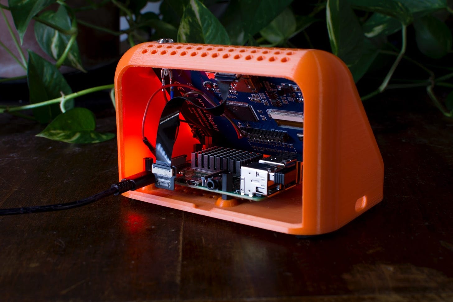
Once the basic shell and the opening for the LCD are finished, I move on to details like openings for cable connectivity, the backdoor and some breathing holes along the top and the front.
At this point, the back cover also receives a basic design, carving it out of the back door opening. It gets matching breathing holes, and a finger-sized opening for easy removal. How the back door is held in place is left for a later stage, once there’s more detail finalised in the main structure, to avoid collision conflicts.
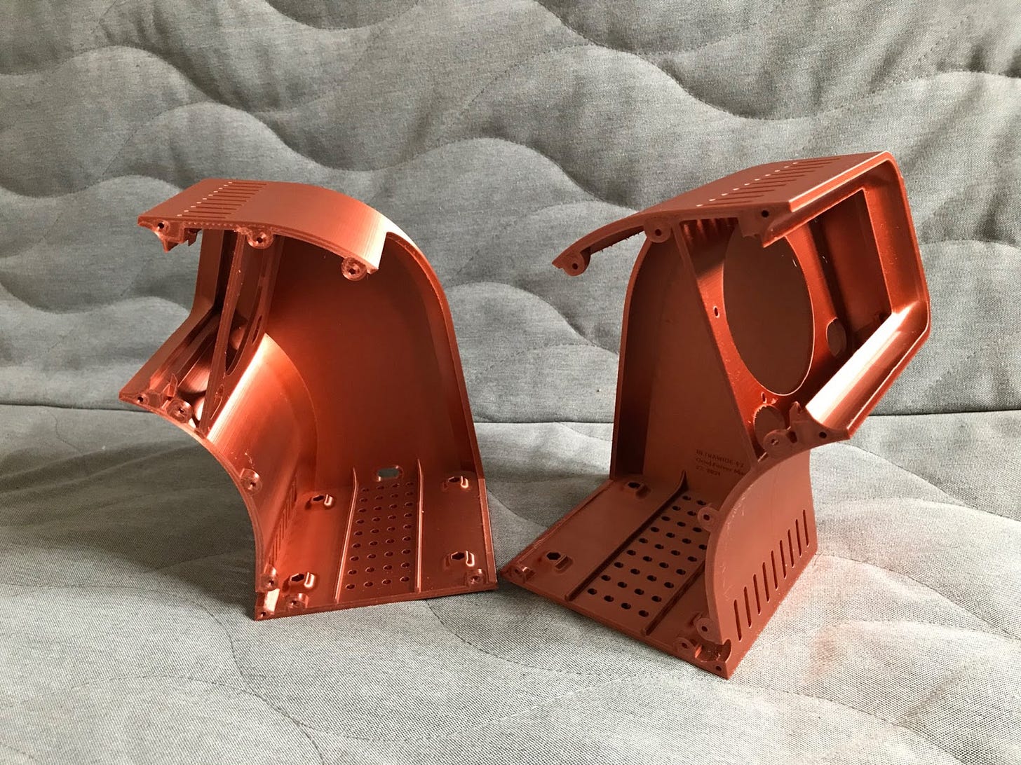
With this terminal being on the larger side (244mm wide), I chose to add structural reinforcements along the bottom, to counter the breathing holes placed along the bottom that weaken the structural strength. I also added a completely new structural wall (albeit with very large holes) along the whole width, to both make the structure more robust and to mount the LCD controller board. The controller board will be mounted with nylon bolts and nuts, and to do so I needed to make perfectly measured holes that match the layout on the board. This kind of reinforcement is often the result of getting the design close to a finished state, printing it, realising it feels too weak for comfortable handling, and going back to the original design to reinforce it.
The LCD will be slotted into the perfectly measured opening, across the mid-split, that separates the two prints. It will be held together with small triangular protrusions along the width of the screen. Note that the protrusions come in this shape as a constraint found later during the printing process — having this pointy shape allows printing them without the need for structural supports.
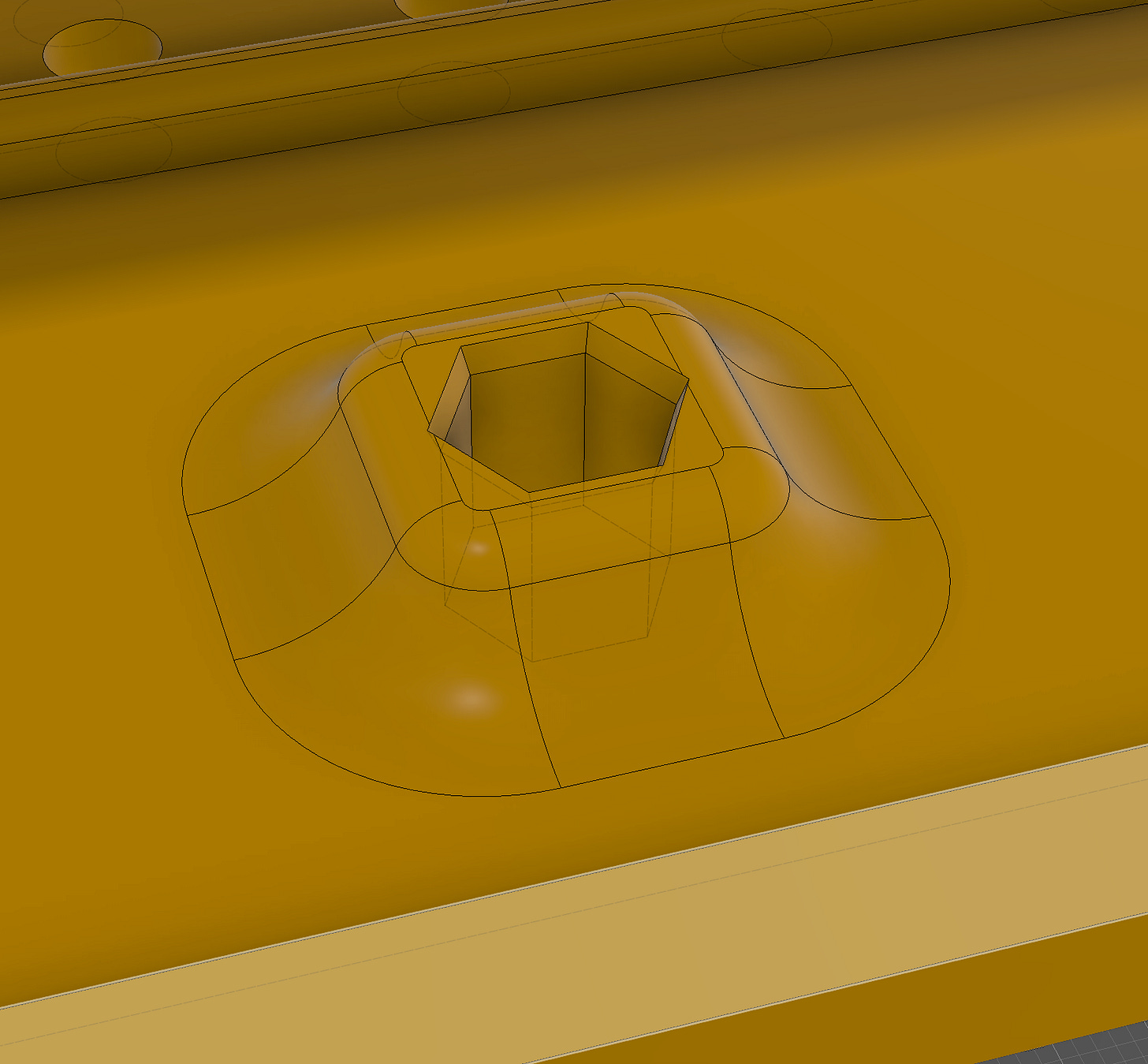
I add sockets that will hold the single-board computer and any other components that are needed. Those are hex-shaped holes, precisely carved to allow easy insertion and removal of M3 stackable nylon standoffs, making it very easy to swap in and out components between computers. There will be one stack per “side” of the computer, each held with four of these standoffs.
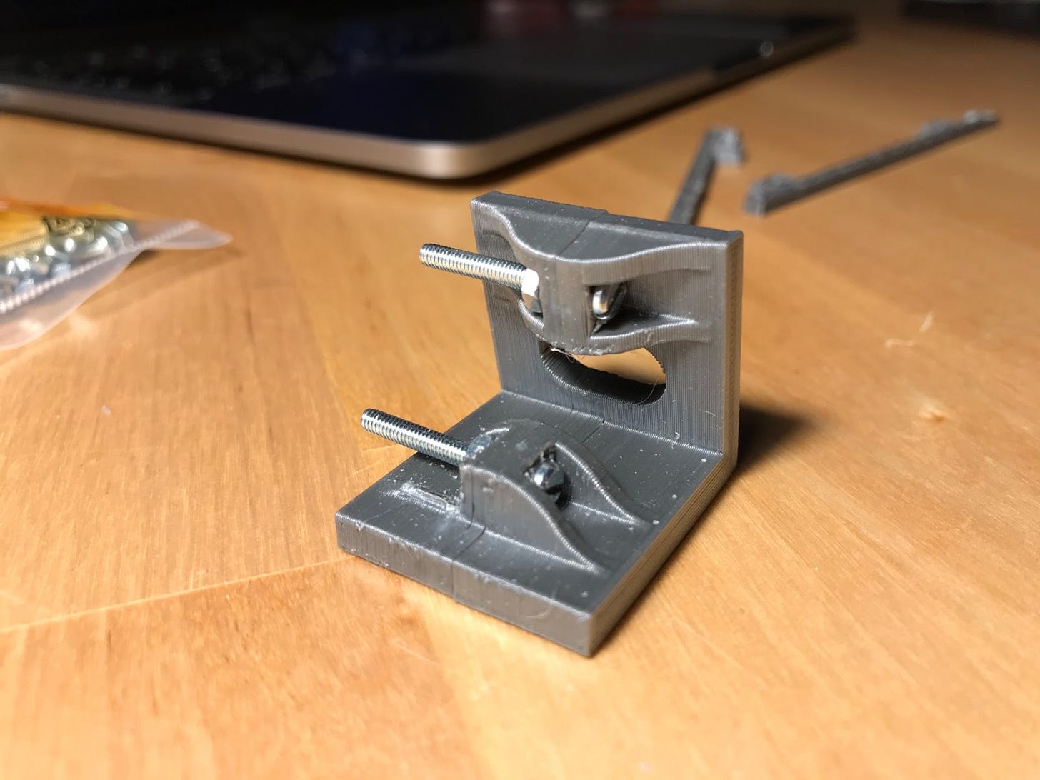
At this point the model can be split into the two parts that will need to be printed separately (to fit in my printer, which has a 22x22 cm bed size). As this computer requires two printed parts, a good plan is needed to assemble and keep them together tightly. To achieve this, I used a custom modular component I designed for other multi-part prints, basically attachment points for fastening bolts. I placed several instances of this component along the seam that divides the two parts, taking into account that a bolt will need to be able to be reached with a screw-driver or similar.
Next is finishing up the back access panel, giving it a pressure-fit mount, so that internals of the computer can be accessed without using tools. A set of protruding structures with different shapes is designed, so that the backdoor can be closed by simply applying a bit of pressure, and easily opened with the pull of a finger. The bottom of the panel is inserted into the rail first, and the top is then pushed against the structure until it “clicks” into place.
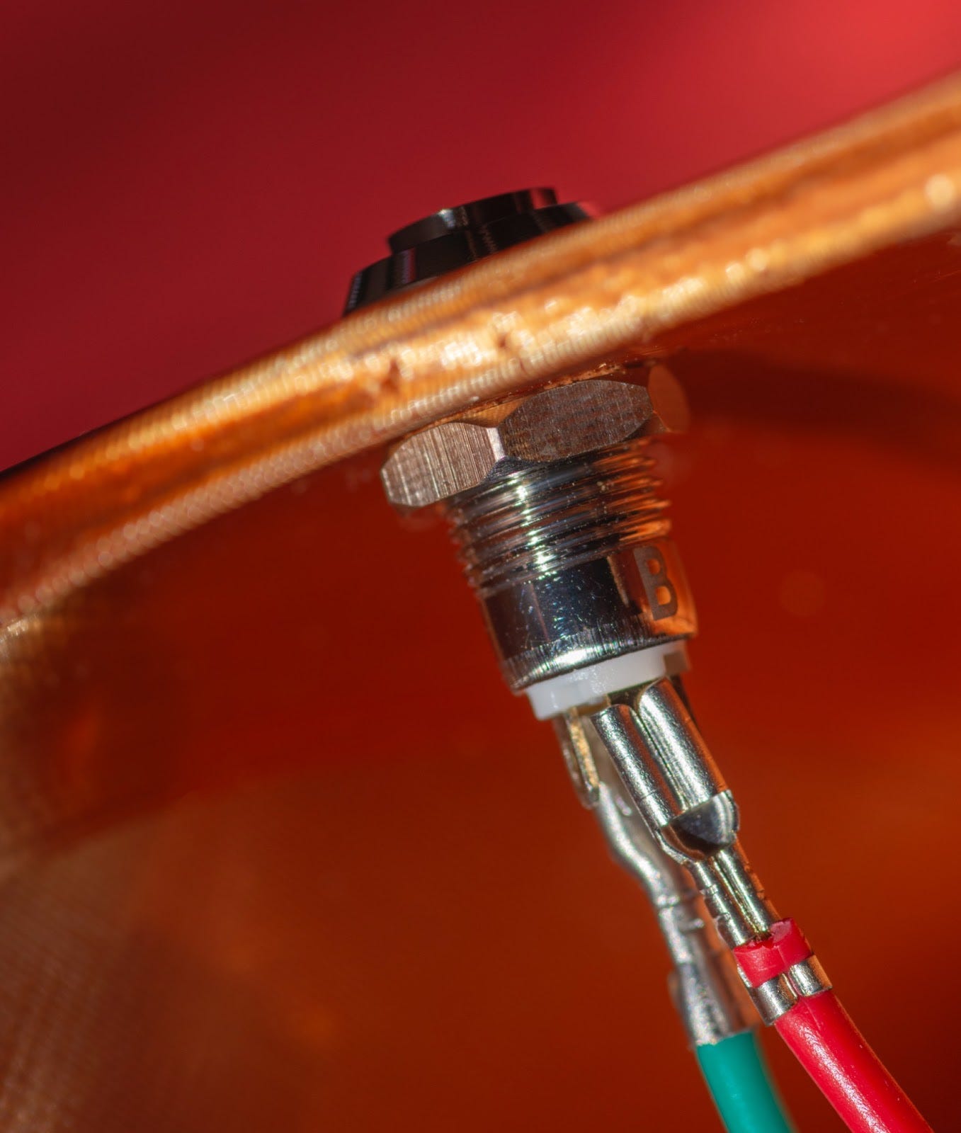
Next is creating the structures that will hold the components stack, including the Jetson Nano 2GB board and the speaker. Those are just flat shapes that adapt the standoffs disposition imprinted at the bottom of the computer to the board layout holes in the components that need mounting. I also made a hole that fits a power switch for the LCD, that will allow controlling its power independently from the computer power state.
3D Printing: Where the waterfall model fails
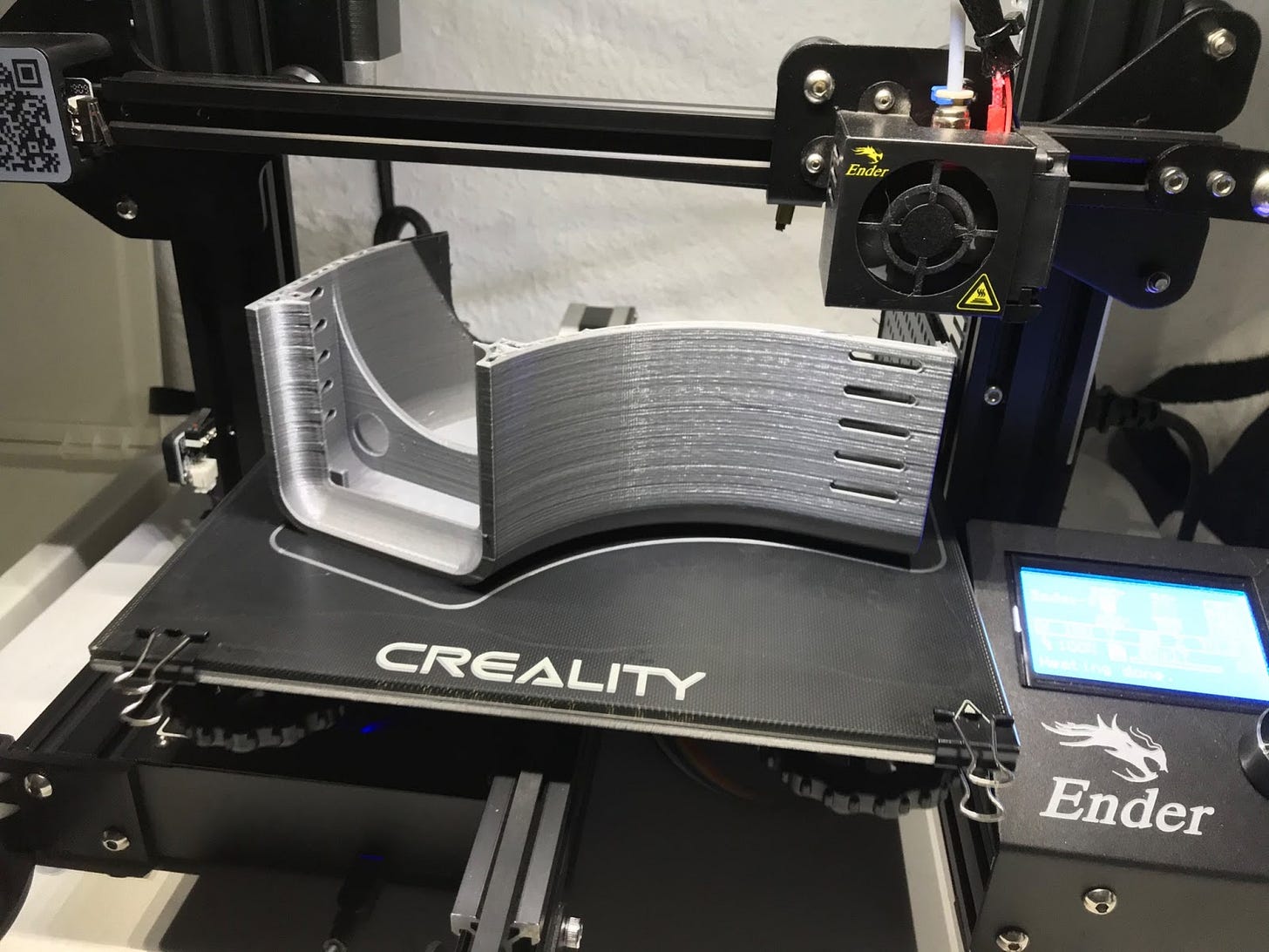
Once you have a finished design, you probably want to see it in the physical world. In this project, the goal was to make this happen with my existing 3D printer, a Creality Ender 3. While doing so, your unconstrained object meets an uncomfortable reality; not everything you can design or image is printable in the real world. In fact, your design will be highly limited by the printing technology you use (in my case, FDM).
Facing this reality was often hard and demoralizing, as it usually required major redesigns. Especially at the beginning (when you lack the necessary intuition). The problems kick in very late, when you think your design is finished and it’s already being printed. The upside is that, as mistakes are made and solutions or workarounds are found, experience and intuition are accumulated. The challenge thus lessens over time, as it forces you to be more aware of the printing constraints during the whole design phase, often influencing or moving it into different directions.
Another big frustration factor is the time it takes to print large volumes, often taking full days.
I often found myself needing to speed up the design and print cycle, testing while still in the design phase how a single part of the model would print, before having to wait for the design to be completed. Some parts of the design are just structural supports for other parts that get designed later, and you just can’t afford the risk of a foundational section of your design maybe being unprintable in your desired orientation. So you print it isolated, validating it early.
A similar thing happens with parts that require very tight tolerances, like for example the slot that holds the LCD. These kinds of parts are very dependent on how accurate your measurements (or the measurements on the datasheet, if you are lucky enough to get one) are. Even if your measurement is accurate, often just by how it gets printed, PLA can add extra thickness here and there, and a fraction of a millimeter is enough for things to not fit, or be too loose. So often the first thing I start with is testing them individually.
One very important constraint to nail down early is in which orientation will your part be printed. Deciding this early will allow you to use this information to your advantage, and ignoring it will likely make you run into walls at print time.
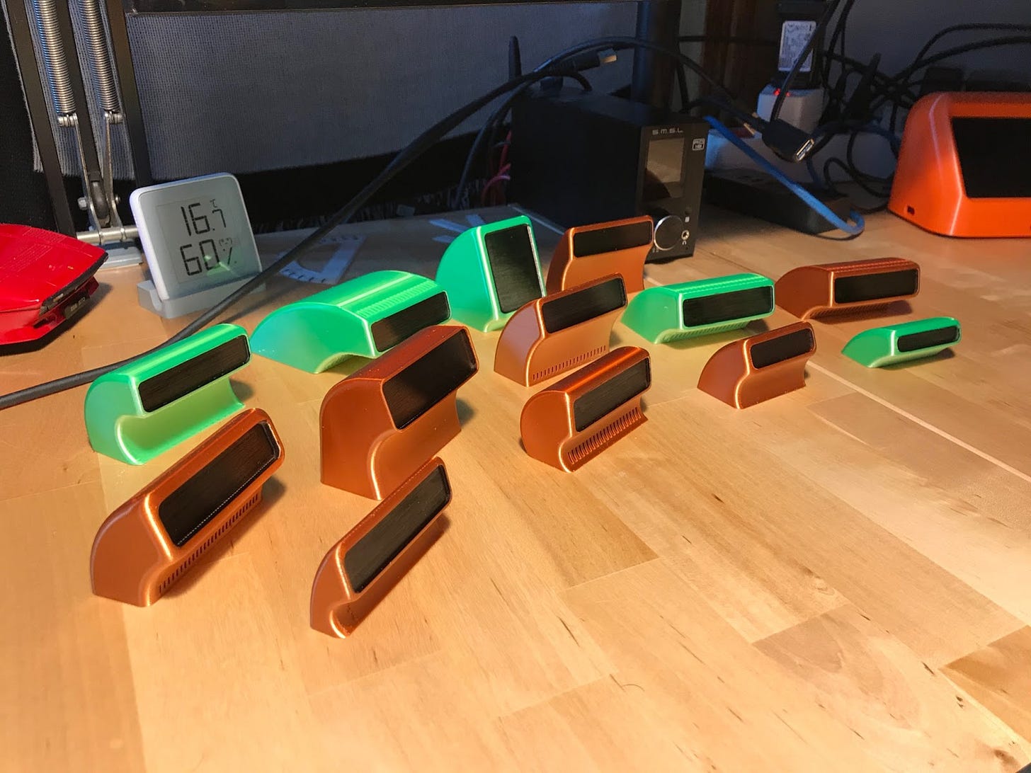
Another way to speed up the printability of a particular model is to just print it, but at a smaller scale. Printing anything into a 50% scale usually speeds up print time 4x. I regularly print tests at 30-25% scale for a very quick feedback loop (as fast as one can get when 3D printing). Printing smaller versions of your model can be useful for a structural preview, but also to visualize the design in the real world, which seems to always reveal some truth that just does not translate as easily when viewed on screen. Nothing beats holding something on your hands to really understand it.
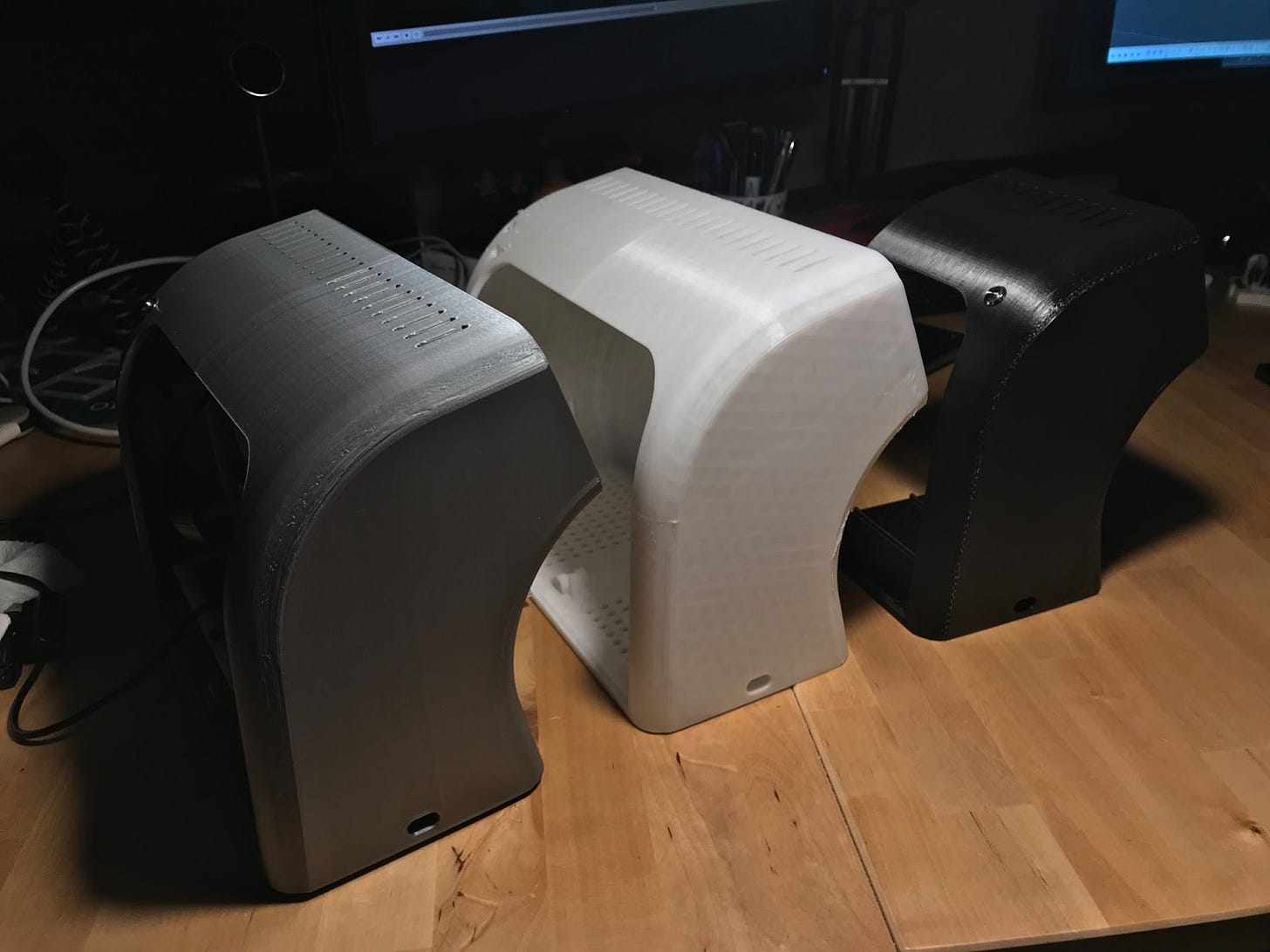
The printing material of choice is also a major decision, not only for color but also texture, print reliability, model strength, and many other factors. Here are some examples of different types of PLA, and how it affects the look. Just the difference between a matte, a plain or a “silk” PLA is huge.
One often overlooked step that can be very time consuming is the removal of print supports. For some printed parts, the use of supports is unavoidable because of their shape, and this can lead to very tedious and delicate work being needed after every print. A good example of this is the curved backdoor for this computer, which depending on the chosen material, required some serious force to remove.
Putting it together
After printing this particular model, we end up with two parts. But the goal is for them to work together as if they were a single part, and to hide the seam as much as possible. We place the LCD on its socket, aligning both sides carefully, and start screwing the nuts into the bolts.
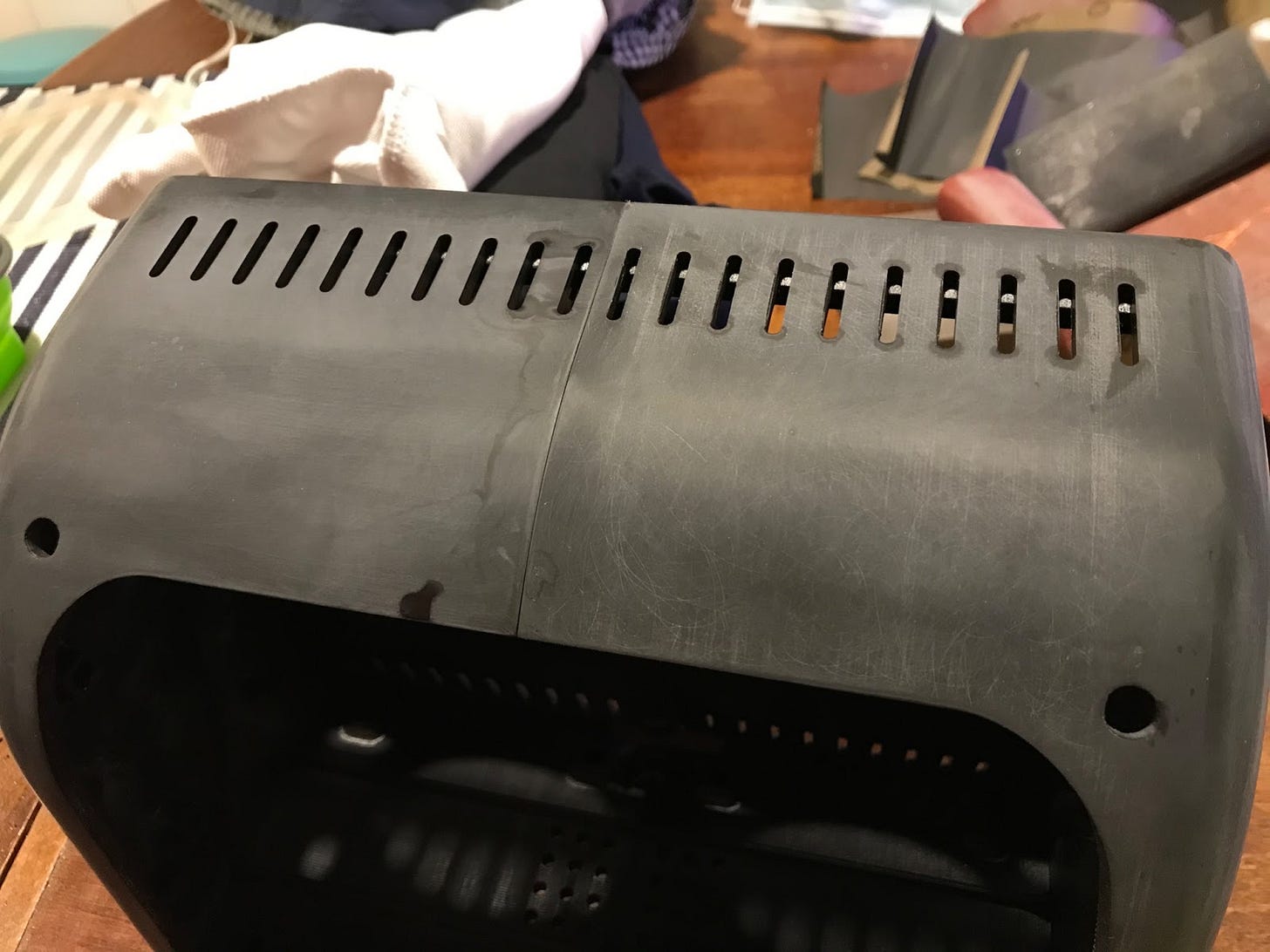
Doing this results in a single strong object, with a minimal seam in the middle. But depending on the material of choice, because of how the independent parts are printed in different directions, it can lead to the color of each side looking quite different.
Finishing touches
Once the enclosure is printed, the tolerances allow for a successful assembly, and the LCD fits nicely in the enclosure, it is time to start thinking about how to hold the rest of components inside the computer securely.
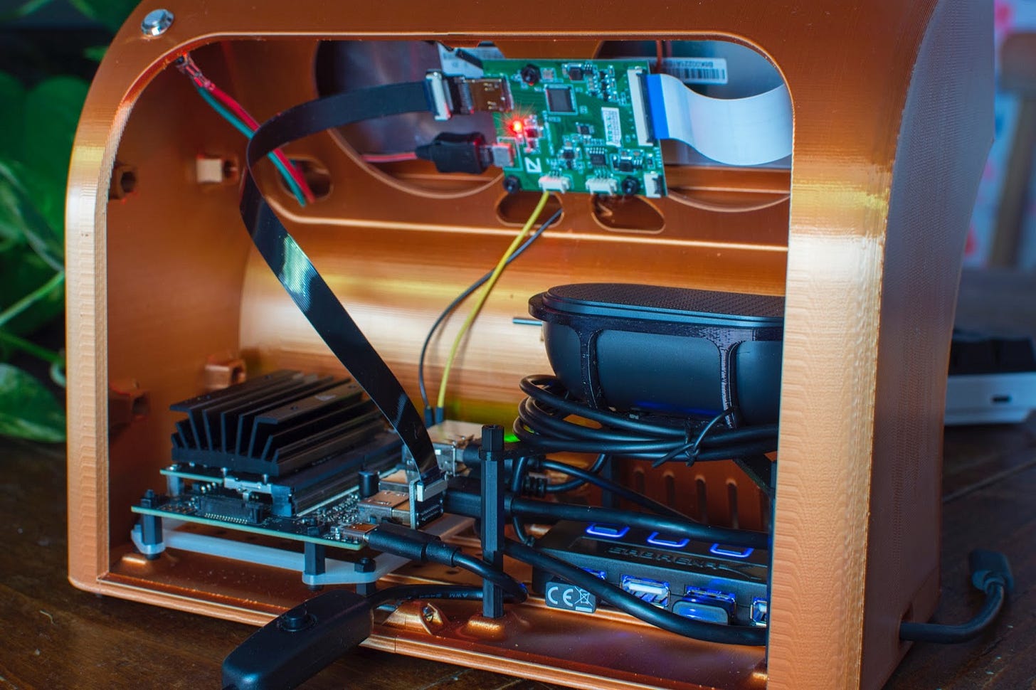
Common components include the LCD circuit board, the single-board computer, and a speaker is often a nice complement to include in a build as well. It's nice to be able to quickly swap components between different computers, especially to test out how a new design looks and feels without having to order (and wait for) a whole new batch of components to test it out with. As a consequence, over the different terminals I built, my designs converged towards a modular system to support easy component swap-ins. I needed something that would hold the components strongly enough, that required no tools to add or remove components, and that it could accommodate any number of components. Through trial and error, I landed on M3 stackable screwable standoffs. The case is built with four sockets that allow pressure-fitting standoffs into them, with a pretty secure placement, and whilst still allowing easy removal of the socket, without any tools.
Another very important part of the assembly is cabling. Quite a few cables are required for the computer to operate, and particularly HDMI cables are hard to come by in sizes that make sense for such constrained spaces. Luckily I found a solution from a manufacturer from China that sells all standard HDMI connectors in any 0º, 90º and 180º orientation, and swappable ribbon cables to pair them. This is great because you can mix and match for any connector configuration you need, and then choose the right ribbon length. The cables take a very minimal amount of space, especially when compared to the amount of space a traditional HDMI cable would.
It’s often desirable to be able to leave the computer running whilst the screen is turned off. Some of the LCD boards come with blanking / sleep support, but some don’t. For those that don’t, I usually place a power switch near the screen, that allows the user to power the LCD on or off.
The single-board computer is usually powered by a small 5V power supply. To avoid having to unplug it from the wall when the computer is off (most single-board computers stay powered even after the OS shuts down), it’s nice to add an external power switch to cut / restore power. I use a short USB extension with an integrated switch for this, and it does the job quite nicely.
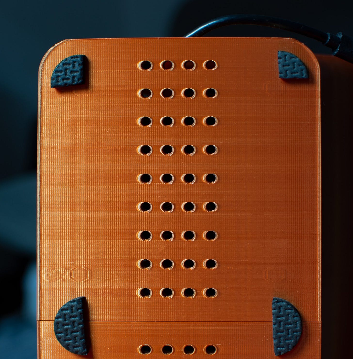
The grip of PLA against most surfaces is not so great, so just placing the computer on a flat surface doesn’t quite feel right. I always install some rubber/foam feet, which also helps with the cooling (by separating the bottom ventilation holes from the target surface).
Improving the finish
I was never satisfied with the final quality of the printed models; PLA is a great material for prototyping, but the finish is not quite there. There’s often visible imperfections, no matter how small the layer height you choose while printing, and doing so extends printing times even further. While exploring ways to improve the looks of the final models, I started following the rabbit-hole that is smoothing out the prints, slowly smoothing out the model manually, using wet sandpaper of increasingly higher grit levels. This is very very time consuming, and you can easily, at any time, damage the model in the process... to a point where you’d need to start over with a new print. But if you do it carefully and patiently, the results can be very good.
Applying some plastic polish cream with wool also leads to great shiny looks, sometimes achieving very convincing glossy results. But there’s always the risk of going too far and blemishing the print completely, requiring a re-print, re-sanding and re-polish… So it is a very demanding process, and it presumes you have no rush at all.
Using an airbrush to paint over the smoothed-out models can also lead to amazing results, but it is yet another whole can of worms. Learning how to use an airbrush takes time and skill. There’s tons of primers, paints, and other chemicals out there to try out, and yet again it is very easy to spoil a whole lot of work with a single mistake. The results can be very worth it, but they will only be if the sanding process from the previous is absolutely perfect. Any imperfection on the substrate will really stand out, and the more polished the finish gets, the more a single scratch stands out. Varnishing can also be an option to give the paint extra durability, or a glossy coat if desired.
The Final Object
With enough time, effort, and a willingness to learn new things, one can nowadays design and manufacture a whole range of objects right from home. It only takes a computer, some (free) software, an inexpensive 3D printer, and some money for ordering parts. I for one am very grateful that all of this is possible today, and very excited about what to make next.
My background pushes me towards solving a whole range of problems, but the challenges I encountered while designing these computers felt very different, and extremely refreshing.










Hi man, lovely design!
Do you have the STL or STEPs for the project, in particular I Love the 4:3.
Thank You!